MRI Emulator
Class: NodeMRIEmulator
This node is a tool for emulating magnetic resonance images for various imaging setting. It can generate contrast for spin-echo and gradient echo sequences, add realistic noise as well as simulate effects such as aliasing and fat-water-shift. Output is an image and an estimated imaging time. The node is based on the BrainWeb Phantom and two different brains datasets are available.
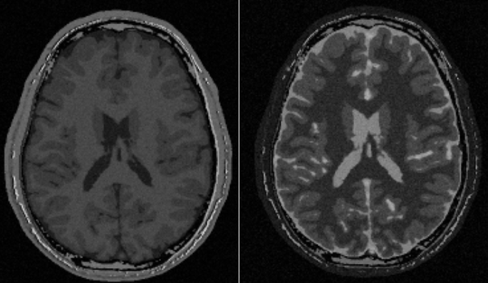
Figure 1: Examples of some of the images that can be created using the node.
Outputs
MR Image
Magnitude MR image.
Type: Image4DFloat
Imaging time
An estimate of the imaging time.
Type: String
Settings
Phantom
Subject Selection
Select dataset from which the MR images should be generated.
Values: Subject04, Subject05
Tissue Parameters Text
Edit the tissue specific parameter values used in the image generation.
Geometry
Settings determining the geometry of the generated image.
Matrix X Integer
Number of pixels in x-direction.
Matrix Y Integer
Number of pixels in y-direction.
Matrix Z Integer
Number of pixels in z-direction.
Resolution X [mm] Number
Resolution in x-direction, i.e. the size (in mm) of a pixel in the x-direction.
Resolution Y [mm] Number
Resolution in y-direction, i.e. the size (in mm) of a pixel in the y-direction.
Resolution Z [mm] Number
Resolution in z-direction, i.e. the size (in mm) of a pixel in the z-direction.
Position offset RL [mm] Number
Image offset in the x-direction.
Position offset AP [mm] Number
Image offset in the y-direction.
Position offset SI [mm] Number
Image offset in the y-direction.
Rotation axis RL Number
Oblique slices can be obtained by rotating the image around an axis given in three coordinates in (RL, AP, SI) directions. This setting specifies the rotation axis component in RL-direction. The rotation vector does not need to be normalized.
Rotation axis AP Number
Oblique slices can be obtained by rotating the image around an axis given in three coordinates in (RL, AP, SI) directions. This setting specifies the rotation axis component in AP-direction. The rotation vector does not need to be normalized.
Rotation axis SI Number
Oblique slices can be obtained by rotating the image around an axis given in three coordinates in (RL, AP, SI) directions. This setting specifies the rotation axis component in SI-direction. The rotation vector does not need to be normalized.
Rotation Angle [degrees] Number
The angle to rotate the image around the rotation axis. See the setting: Rotation axis RL/AP/SI.
System
System related settings, such as field strength.
Fieldstrength Selection
Select field strength of the scanner. Note that this setting only affects the SNR. To change tissue parameters such as T1 and T2 use the Tissue Parameters setting.
Values: B1_5T, B3T
Imaging coil Selection
Select imaging coil. This will impact the SNR. The IdealCoil value will produce an image with no noise.
Values: BodyCoil, HeadCoil, IdealCoil, FlexCoil
Maximum Gradient Strength [mT/m] Number
Select maximum gradient strength of the scanner. Currently this setting has no effect.
Sequence
Sequence Name Selection
Select sequence. Currently the Fast spin echo only differs from spin echo in terms of imaging time.
Values: SPGR, SE, IRSE, FSE, IRFSE
Sequence Type Selection
Select type of imaging.
Values: dim2D, dim3D
Phase endocing direction Selection
Select the phase encoding direction.
Values: dirX, dirY
Pixel bandwidth [Hz] Number
Bandwidth per pixel in Hertz.
Number of averages Number
Number of images that are averaged.
Parallel imaging factor Number
Parallel imaging acceleration factor. Affects SNR.
Use partial Fourier Boolean
Use partial Fourier to accelerate the imaging (Partial Fourier factor = 5/8).
Repetition time [ms] Number
The repetition time.
Echo time [ms] Number
The echo time.
2D settings
Slice gap [mm] Number
Slice gap in z-direction. Will not affect the resolution or image coverage. Only SNR will be affected since the effective slice thickness is decreased.
Inversion recovery settings
Inversion time [ms] Number
The inversion time.
Real reconstruction Boolean
Reconstruct real images
SPGR settings
Flip angle [deg] Number
The exitation flip angle.
References
1. http://www.bic.mni.mcgill.ca/brainweb/
2. C.A. Cocosco, V. Kollokian, R.K.-S. Kwan, A.C. Evans : "BrainWeb: Online Interface to a 3D MRI Simulated Brain Database" NeuroImage, vol.5, no.4, part 2 / 4, S425, 1997-- Proceedings of 3 - rd International Conference on Functional Mapping of the Human Brain, Copenhagen, May 1997.
3. R.K.-S. Kwan, A.C. Evans, G.B. Pike : "MRI simulation - based evaluation of image - processing and classification methods" IEEE Transactions on Medical Imaging. 18(11):1085 - 97, Nov 1999.
4. R.K.-S. Kwan, A.C. Evans, G.B. Pike : "An Extensible MRI Simulator for Post - Processing Evaluation" Visualization in Biomedical Computing(VBC'96). Lecture Notes in Computer Science, vol. 1131. Springer-Verlag, 1996. 135-140.
5. D.L. Collins, A.P. Zijdenbos, V. Kollokian, J.G. Sled, N.J. Kabani, C.J. Holmes, A.C. Evans : "Design and Construction of a Realistic Digital Brain Phantom" IEEE Transactions on Medical Imaging, vol.17, No.3, p.463--468, June 1998.
6. B. Aubert-Broche, D.L. Collins, A.C. Evans: "A new improved version of the realistic digital brain phantom" NeuroImage, in review - 2006.
7. B. Aubert-Broche, M. Griffin, G.B. Pike, A.C. Evans and D.L. Collins: "20 new digital brain phantoms for creation of validation image data bases" IEEE TMI, in review - 2006
See also
Keywords: Magnetic resonance imaging, Image generation
Copyright © 2022, NONPI Medical AB