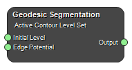
Geodesic Segmentation
Class: NodeImageGeodesicSegmentation
Segments structures in images based on a user supplied edge potential map. An initial contour is propagated outwards (or inwards) until it “sticks” to the shape boundaries. This is done by using a level set speed function based on a user supplied edge potential map.
This filter requires two inputs. The first input is a initial level set. The initial level set is a real image which contains the initial contour/surface as the zero level set. For example, a signed distance function from the initial contour/surface is typically used (see e.g. Maurer Distance). The initial contour does not have to lie wholly within the shape to be segmented. The initial contour is allow to overlap the shape boundary. The extra advection term in the update equation behaves like a doublet and attracts the contour to the boundary. This approach for segmentation follows that of Caselles et al.
The second input is the feature image. For this filter, this is the edge potential map. General characteristics of an edge potential map is that it has values close to zero in regions near the edges and values close to one inside the shape itself. Typically, the edge potential map is computed from the image gradient.
Example Workflows
Inputs
Initial Level Set
The initial level set.
Type: Image4DFloat, Required, Single
Edge Potential
Edge potential map. Edges should be ~0 and ~1 elsewhere.
Type: Image4DFloat, Required, Single
Outputs
Output
Output map. To produce a segmentation, this map needs to be thresholded. Negative values in the output image represent the inside of the segmented region and positive values in the image represent the outside of the segmented region. The zero crossings of the image correspond to the position of the propagating front.
Type: Image4DFloat
Settings
Advection Scaling Number
An advection term \(\mathbf{A}(\mathbf{x})\) is constructed from the negative gradient of the edge potential image.
\(\mathbf{A}(\mathbf{x}) = -\nabla g(\mathbf{x})\)
This term behaves like a doublet attracting the contour to the edges.
Curvature Scaling Number
In general, the larger the curvature scaling, the smoother the resulting contour.
Propagation Scaling Number
Sets the inflation force, i.e. higher value gives faster propagation.
Maximum RMS Error Number
This parameter is used to determine when the solution has converged. A lower value will result in a tighter-fitting solution, but will require more computations. Too low a value could put the solver into an infinite loop unless a reasonable NumberOfIterations parameter is set. Values should always be greater than 0.0 and less than 1.0.
Reverse Expansion Direction Boolean
Reverses from expansion to contraction, or vice versa.
Iterations Integer
Set the number of iterations.
References
- “Geodesic Active Contours”, V. Caselles, R. Kimmel and G. Sapiro. International Journal on Computer Vision, Vol 22, No. 1, pp 61-97, 1997
- Geodesic Active Contours in SimpleITK
See also
Keywords: segmentation, active contours, snakes
Copyright © 2022, NONPI Medical AB