B0 Distortion
Class: NodeB0Distortion
Produces the distortions created by B0 inhomogeneities. The input values are the image matrix together with the \(\Delta B_0\) map and patient mask.
Inputs
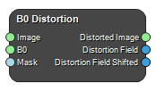
Image
The input image which is to be distorted.
Type: Image4DFloat, Required, Single
B0
The \(\Delta B_0\) map.
Type: Image4DFloat, Required, Single
Mask
A mask which is TRUE within the patient and FALSE elsewhere.
Type: Image4DBool, Required, Single
Outputs
Distorted Image
The distorted image.
Type: Image4DFloat
Distortion Field
The distortion field in mm.
Type: Image4DVector3
Distortion Field Shifted
The distortion field in mm with the bulk avarege distortion removed.
Type: Image4DVector3
Settings
Positive Shift X Boolean
Sets the direction of the x-gradient in relation to the image matrix
Positive Shift Y Boolean
Sets the direction of the y-gradient in relation to the image matrix
Positive Shift Z Boolean
Sets the direction of the z-gradient in relation to the image matrix
Bandwidth X (Hz/Voxel) Number
The applied bandwidth (frequency encoding) in the X-direction given in Hz/Voxel
Bandwidth Y (Hz/Voxel) Number
The applied bandwidth (frequency encoding) in the Y-direction given in Hz/Voxel
Bandwidth Z (Hz/Voxel) Number
The applied bandwidth (read out) in the Z-direction given in Hz/Voxel
Gyromagnetic Ratio (Hz/T) Number
The gyromagnetic ratio to use. Typically this is the default value of 42.57e+6 Hz/T
References
- J A Lundman, M Bylund, A Garpebring, C Thellenberg Karlsson, T Nyholm. Patient-induced susceptibility effects simulation in magnetic resonance imaging. Physics and Imaging in Radiation Oncology. (2017) DOI: 10.1016/j.phro.2017.02.004
- “The Insight Segmentation and Registration Toolkit” www.itk.org
See also
Keywords:
Copyright © 2022, NONPI Medical AB